| rn
TRANSMISSION REBUILD NOTES (Not Yet Completed):
rn
The transmission rebuild is pretty straight forward, IF you follow the manual located here: 1958 - 1982 Transmissions This is one of those time where "RTFI" comes into play. This manual covers the following transmissions: 5003, 5007, 5010, 5025, 5046-5051, 5053, 5058, 5060, 5071, 5073, 5080, 5084, 5086, 5071, 5073, 5080, 5084-5086, 5091, 103907, and 103916 alike. The manual instructs on the procedure for disassembly and reassembly, but does not tell you what "right " looks like, nor does it tell you all the little tricks and/or intermediate steps required in order to do a professional job. This section is intended to inform you of the pitfalls and details you'll likely need in your transmission rebuild.
rn
Disassembly: Follow the process described in the manual. Remember "RTFI".
rn
Part inspection after disassembly: The following pictures indicate what you are likely to find inside of a 50 y/o transmission. I'd like to thank "tgranthamfd", (Terry in Oklahoma, from the Red Square Bulletin Board) for the pictures of his transmission rebuild, as I did not take pictures of my own during the process.
rn
rn
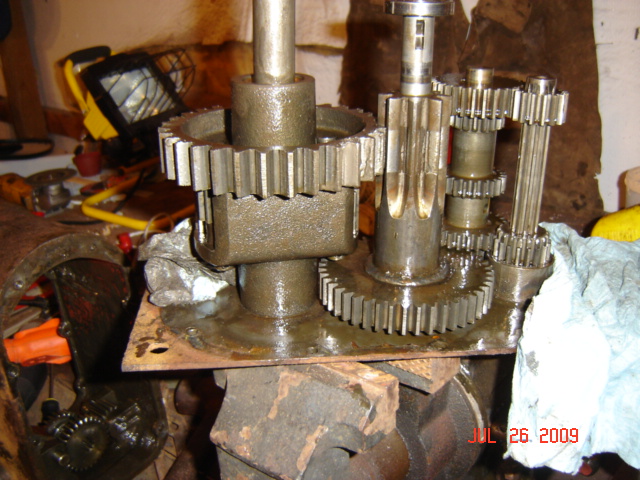
- By the time you get the case off the transmission you'll be presented with a view like that in picture 1 below.
rn
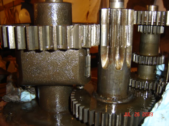
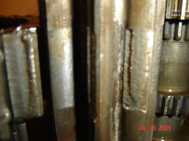
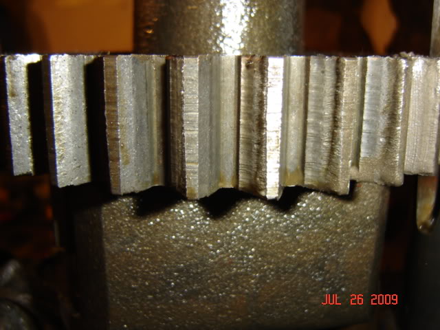
- The most important first place to inspect is the teeth between the Differential and Brake Shaft Gears (foreground of picture 2), these are a "matched set" and should be replaced as a pair if they are overly worn. You will probably see a small amount "gouging" in the teeth of the Brake Shaft Gear, and you may see much less, but some, on the Differential Gear teeth. This is normal as these gears would "lash" as the tractor rocks forward and back during use. Serious gouging of these teeth would be anything greater than a 0.065" deep (roughly 1/16"), but also depends on how much you plan to use the machine. If this is strictly going to be a show machine, then you could probably get away with as much as 0.100" before requiring replacement. Unfortunately, at this writing (August 2009), part replacements are not available from any manufacturer and scavenging or costly reproduction is the only answer. Small amounts of gouging can be cleaned up with a Dremmel Tool with a small sanding drum or a fine file, by removing only the high burrs and to somewhat level the gear tooth faces and the tops of the gear teeth to the surrounding metal. Do this on both gears as necessary. DO NOT SAND THEM BACK TO A FLAT SURFACE, you will be removing too much material. Pictures 3 and 4 show close-ups of acceptable gouging before cleanup. Once the surfaces have been cleaned up with the Dremmel Tool, clean the parts in a parts washer and set aside covered with a rag to keep shop dust off the parts.
rn
- Inspection of all parts can continue after all assemblies have been cleaned n a parts washer or by hand.
rn
- Generally, all mating surfaces should be measured with a micrometer or digital/dial indicators. Clearances of no more than 0.003" (over and under) are normally acceptable for this vintage of machine. If you have a 3/4" shaft going into a ball bearing, measure the inner race of the bearing and subtract 0.003" (normally, bearing inner races are manufactured to 0.0005" undersized). So long as the shaft is at least that measurement, then the part can be considered "good". Measure all new bearings and measure the associated shafts at the points of contact to insure all parts are within specification.
rn
- In the case of the axle shafts, which in my case are 0.750", measure the shafts at the bronze bearing contact points. These should measure approximately 0.750 (+ 0.000 / - 0.0015). Any more than this and the bronze bearings would leak. If the wear is not acceptable, I have seen where the axle shafts have been drilled to accept a roll pin at the hub end, and the axle shafts reversed in order to get a good surface inside the bronze bearings. The original roll pin hole will be covered by the wheel hub and not visible after final assembly, and this action saves the expense of replacing the axles. The axles must be a close fit inside the bronze bearings or leaking will occur.
rn
- Remove all bearings from the side covers. Good luck, this is a very difficult task. Several of my bearings required the inner and out races to be cut with a Dremmel tool in order to get them out. Any long, flat tool can be used for this purpose, so long as you can get it under the inner race without damaging the surface of the case below the bearing. A thin, sharp pointed chisel or sharpened screw driver will work in a pinch, but a gear puller designed for the purpose is preferred. I purchased bearings from an online source (The Bearing Source) which supplied (made by "General Manufacturing") low cost/good quality ball bearings.
rn
rn |


 Previous